Aerospace Engineer
Liquid Rocket Engine Test Stand

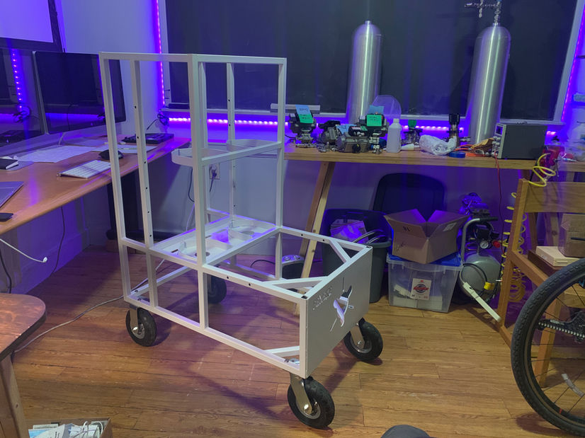
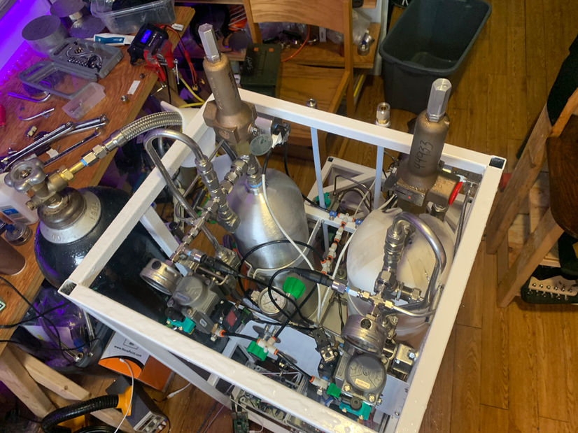
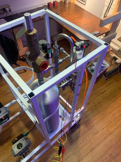
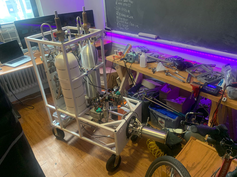
The most time consuming and expensive part of building rocket engines is the system of tanks, valves, and sensors called the test stand. A test stand's main function is to deliver the cryogenic liquid oxygen oxidizer and kerosene fuel at the correct pressure and flow rate to the engine. The stand also has to withstand the thrust of the engine, remotely execute commands, record data, and mechanically shut down and vent pressure in the event of an anomaly or loss of power.
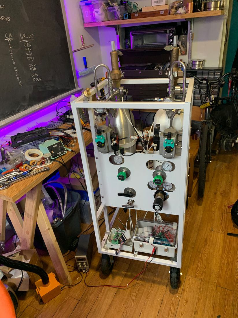
The test stand consists of the following subsystems:
-
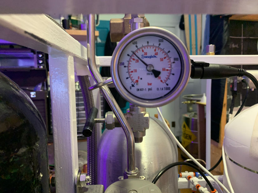
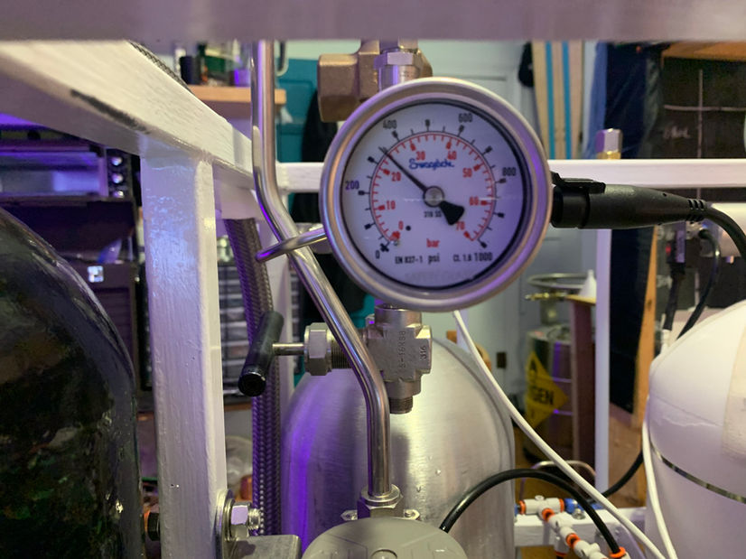
High pressure panel to regulate and distribute the nitrogen pressurant gas to the tanks, fuel/ox purge system, and low pressure pneumatics
-
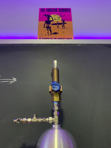
Insulated tanks with relief, vent, fill, and drain valves.
-
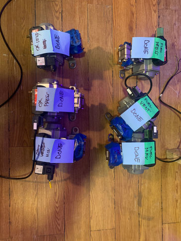
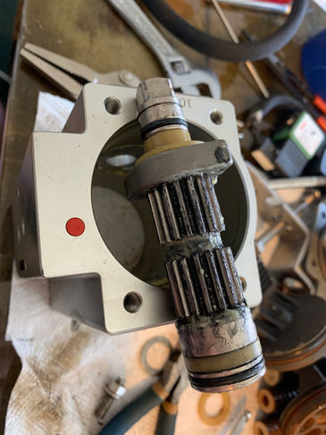
Liquid feedlines with valves modified for cryogenic oxygen service
-
Purge system to clear the engine and propellant lines of residual propellant after shutdown
-
Low pressure pneumatics system to provide gas to pneumatically-actuated valves
-
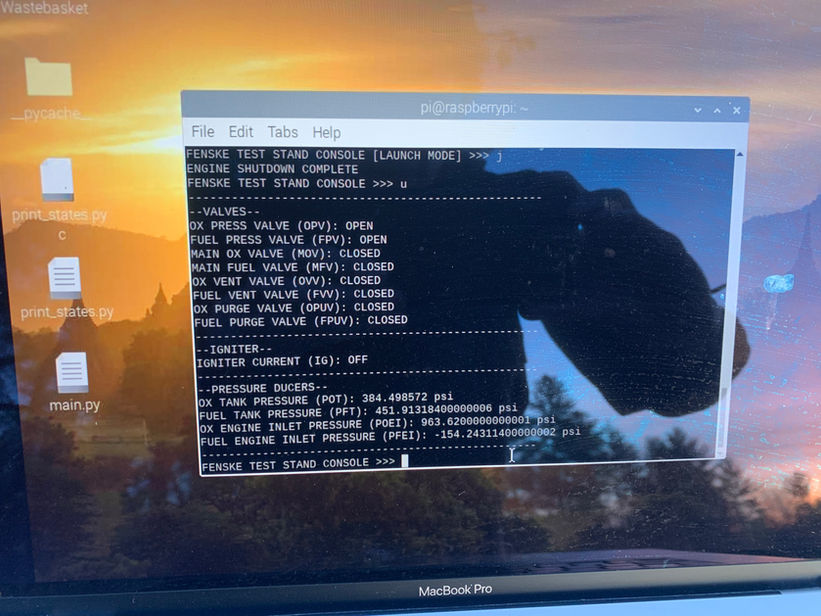
Control system programmed to actuate valves at the precise timing needed to fire a liquid engine
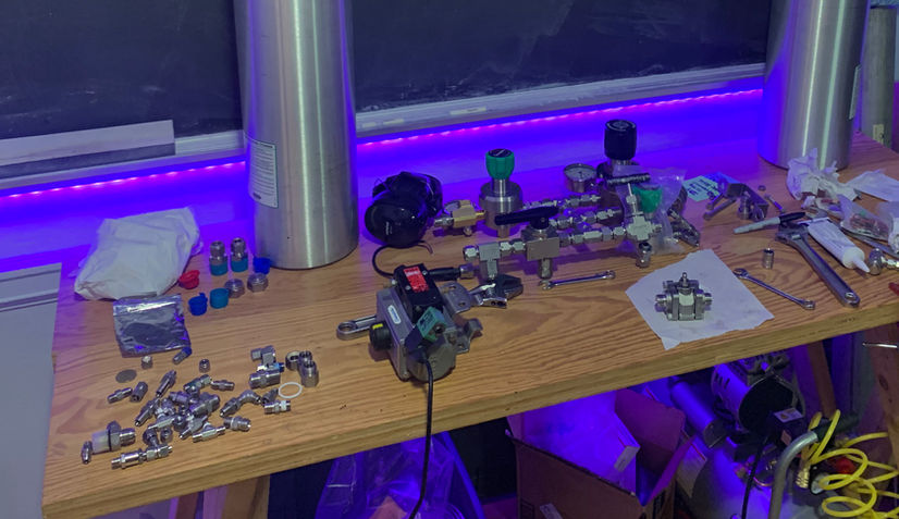
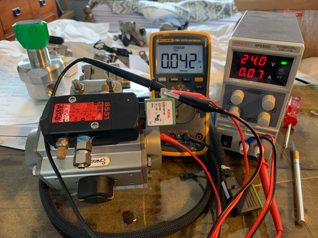
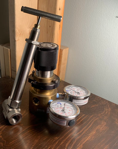
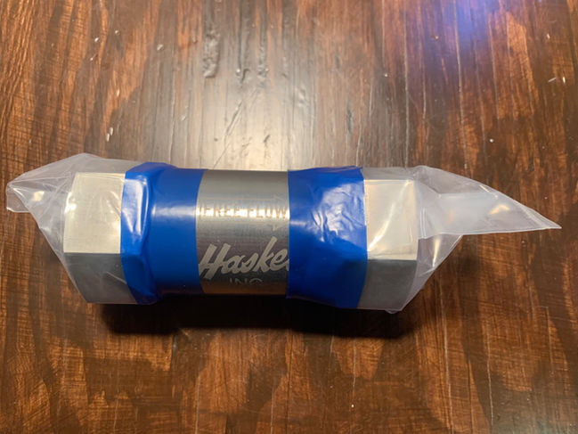
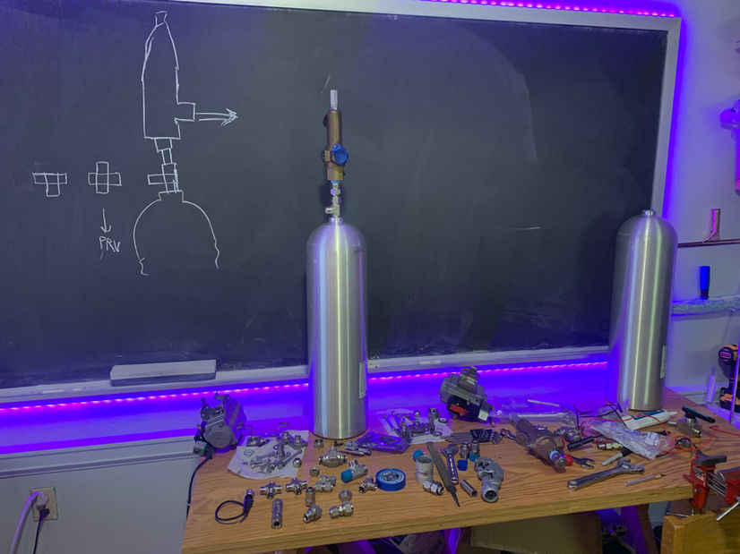
All of these components (even the tube fittings) are typically very expensive or not sold to consumers. I therefore had to buy most components from Ebay or make them myself. After 4 months of work, I was confident that the test stand was a safe system capable of firing liquid rocket engines. During the test of my first engine, the stand worked flawlessly from startup to shutdown. I expect this stand to fire countless more engines in the future.
Static Fire Video
Part I. Fluid System Development


Part II. Test Stand Model


Part III. Manufacturing and Integration
III.i. Fluid System Components



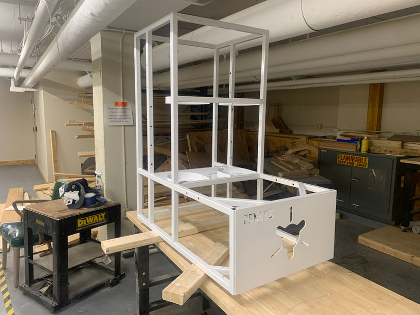
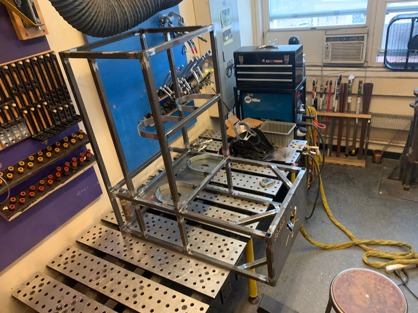
III.ii. Frame Weldment





f
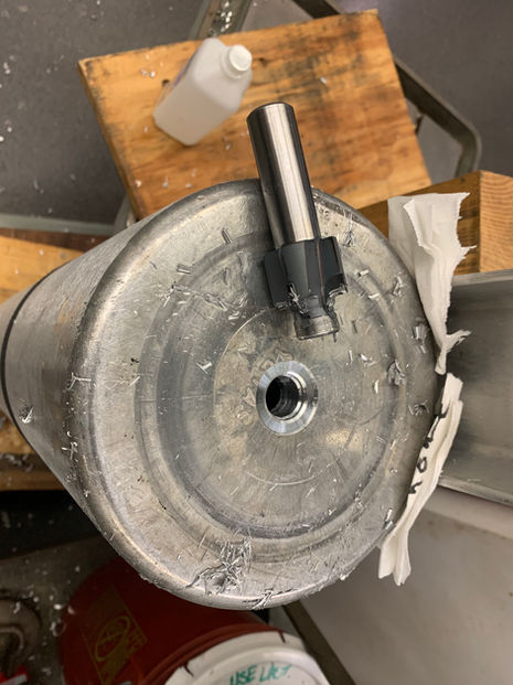
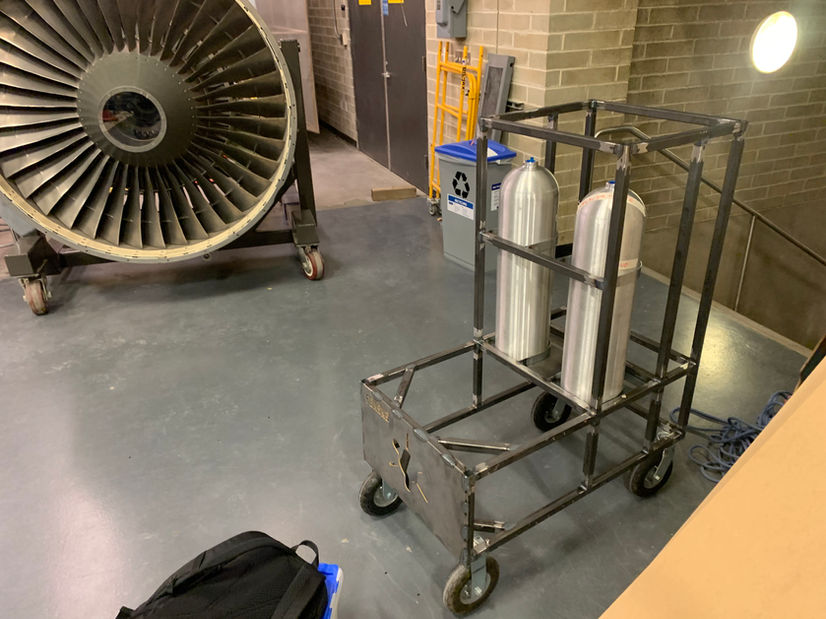
III.iii. Propellant Tanks




III.v. High Pressure Panel


III.iv. Tank Press System



III.vi. Main Propellant Feedlines

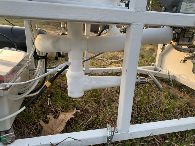

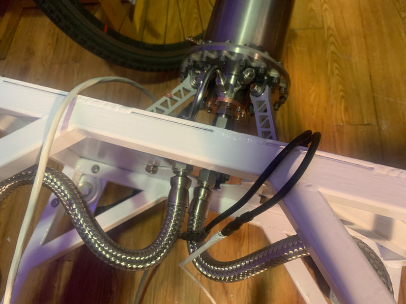


III.vii. Propellant Purge and Pneumatics Systems


Part IV. Control and Instrumentation
IV.i. Avionics
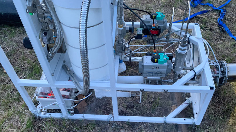

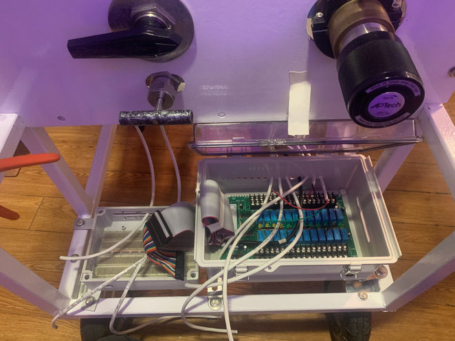


IV.ii. Control Software


Part V. System Characterization
V.i. Relief Valve Setting


V.ii. Fluid System Characterization


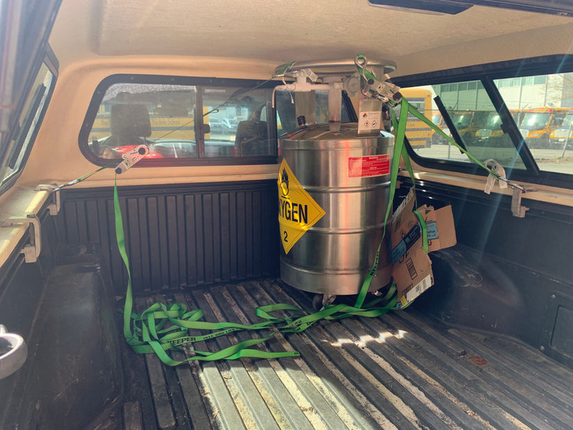
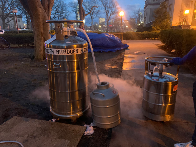
V.iii. LOX Dewar


Part VI. Hot Fire Testing
VI.i. Prop Load


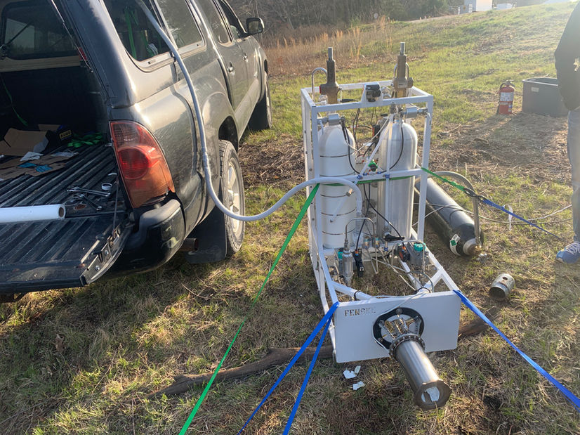
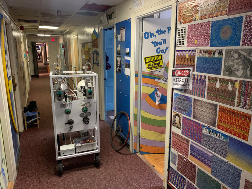


VI.ii. Hot Fire


