Aerospace Engineer
Liquid Rocket Engine

I think liquid rocket propulsion is the the holy grail of engineering. A liquid rocket engine's power-to-weight ratio is orders of magnitude greater than that of car or jet engines and they must be light and strong enough to survive the flight to orbit. There are areas within the injector and combustion chamber where the temperature differential is around -300F to 5000F within a few millimeters. Rocket engines are hard to design and build but I wanted to try anyway.
Typically, only governments, corporations, and large well-funded student teams with support from professors make successful liquid engines. My goal, however, was design, build, and test a liquid engine by myself in four months while taking 6 classes during my final semester at MIT. I used knowledge gained from my internships at SpaceX and JPL, from several textbooks, and advice from friends in the industry.
Since I only had enough time to make one engine, I decided to set very ambitious requirements. After a few trade studies, I decided that the engine should use liquid oxygen (LOX) and kerosene propellants (same combination as the Saturn V and Falcon rockets), produce 5kN (1120 lbf) thrust, and be mass optimized for flight. For propellant injection I designed a pintle type injector with fuel film cooling. Every part except the ablative thrust chamber assembly was designed to be reusable.
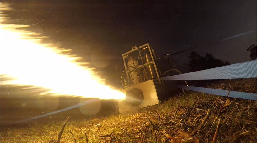
Since the only space I had on campus was my dorm room, I converted it to a bureaucracy-free mini rocket laboratory. Designing, building, and testing this engine (and test stand) took hundereds of hours to complete but I think I learned more from the project than from my 4 years at engineering school. Two weeks before I graduated, I successfully static fired my engine for 3 seconds. Developing this engine has been my most rewarding project yet and I plan to build larger and more efficient engines in the future.
Static Fire Video
Part I. System Modeling and Trade Studies


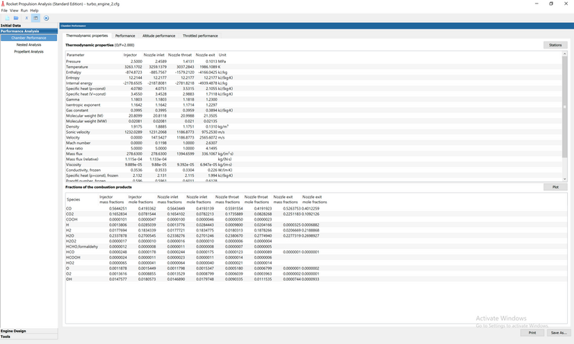
For example, this plot shows Isp vs mixture ratio - an important trade between chamber temperature and specific impulse. Material properties limit the max chamber temperature.


For example, this plot shows Isp vs mixture ratio - an important trade between chamber temperature and specific impulse. Material properties limit the max chamber temperature.


For example, this plot shows Isp vs mixture ratio - an important trade between chamber temperature and specific impulse. Material properties limit the max chamber temperature.


For example, this plot shows Isp vs mixture ratio - an important trade between chamber temperature and specific impulse. Material properties limit the max chamber temperature.


For example, this plot shows Isp vs mixture ratio - an important trade between chamber temperature and specific impulse. Material properties limit the max chamber temperature.


For example, this plot shows Isp vs mixture ratio - an important trade between chamber temperature and specific impulse. Material properties limit the max chamber temperature.


Part II. Mechanical Design and Analysis
II.i. Injector Design Evolution


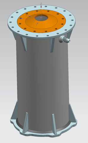
The final injector assembly design balances mass combustion efficiency, and machinability.
This design is centered around the pintle injector design which is known to have no significant combustion instabilities due to the counter-rotating gas flow in the combustion chamber.
Pintle injectors require tight tolerances. This design has simple centering features that are easy to machine and guarantee the fuel flow rate to +/- 10%. To prevent warping, no parts were welded to parts responsible for pintle centering. Instead, the mounting clevises and fuel film cooling port were welded to a flat plate that is bolted over the film cooling duct.
Pintles are also susceptible to melting. Copper, which has a high thermal conductivity, was used to transfer heat from the outer surface of the pintle tip to the liquid oxygen in the inner surface.
Arguably the best part of this injector assembly design is the well distributed fuel flow with little accumulated propellant volume. This ensures efficient and uniform combustion and prevents excess propellant dribble on startup and shutdown.
II.ii. Injector and Propellant Manifold Design


II.iii. Thrust Chamber Assembly (TCA) Design


Part III. Manufacturing
III.i. Injector Plate GD&T


III.ii. Injector Plate Machining


III.iii. Pintle Tip GD&T


III.iv. Pintle Tip Manufacturing


III.v. TCA Manufacturing


III.vi. Integrated Film Cooling / Mounting Plate


III.vii. Integration


Part IV. Testing and Characterization
IV.i. Fuel / Ox Injector Testing


IV.ii. Injector Testing


Part V. Static Hot Fire
V.i. Integration with Test Stand

Unlike other teams and individuals that static fire at established test sites such as FAR or RRS, I had to truck in all the equipment needed to fire the engine.


Unlike other teams and individuals that static fire at established test sites such as FAR or RRS, I had to truck in all the equipment needed to fire the engine.


Unlike other teams and individuals that static fire at established test sites such as FAR or RRS, I had to truck in all the equipment needed to fire the engine.


Unlike other teams and individuals that static fire at established test sites such as FAR or RRS, I had to truck in all the equipment needed to fire the engine.


Unlike other teams and individuals that static fire at established test sites such as FAR or RRS, I had to truck in all the equipment needed to fire the engine.


Unlike other teams and individuals that static fire at established test sites such as FAR or RRS, I had to truck in all the equipment needed to fire the engine.


Unlike other teams and individuals that static fire at established test sites such as FAR or RRS, I had to truck in all the equipment needed to fire the engine.


Unlike other teams and individuals that static fire at established test sites such as FAR or RRS, I had to truck in all the equipment needed to fire the engine.


V.ii. Prop load


V.iii. Hot Fire!


Part VI. Teardown

The black soot on the pintle tip and injector plate is formed by the fuel-rich reaction producing products that condense on metallic surfaces. This acts as thermal insulation, which is one of the benefits of using a kerosene rocket fuel.


The black soot on the pintle tip and injector plate is formed by the fuel-rich reaction producing products that condense on metallic surfaces. This acts as thermal insulation, which is one of the benefits of using a kerosene rocket fuel.


The black soot on the pintle tip and injector plate is formed by the fuel-rich reaction producing products that condense on metallic surfaces. This acts as thermal insulation, which is one of the benefits of using a kerosene rocket fuel.


The black soot on the pintle tip and injector plate is formed by the fuel-rich reaction producing products that condense on metallic surfaces. This acts as thermal insulation, which is one of the benefits of using a kerosene rocket fuel.


The black soot on the pintle tip and injector plate is formed by the fuel-rich reaction producing products that condense on metallic surfaces. This acts as thermal insulation, which is one of the benefits of using a kerosene rocket fuel.


The black soot on the pintle tip and injector plate is formed by the fuel-rich reaction producing products that condense on metallic surfaces. This acts as thermal insulation, which is one of the benefits of using a kerosene rocket fuel.


Part VII. Future Plans
Now that I have an operational liquid engine, there are several directions I can go from here. One path is flying a liquid engine vehicle (vehicle=rocket), which I plan do at some point. This would involve designing flight propellant valves, a rocket air-frame with tanks, and a control system. Since the engine I already have is flight weight, it can be flown with almost zero modifications.
Another path, which I am very excited about, is designing an electric turbopump for the engine, which would drastically reduce the fluid system complexity. Here's an initial sketch of the turbopump. Stay tuned for updates...
